 E-shop
A little smart house with impulse relay
Impulse relays are excellent alternatives for lighting control from multiple locations, but they have not defeated the traditional alternative - crossover switch solutions, one of the reasons for which is perhaps the additional devices, more wires and the additional costs of installation. With the appearance and rapid spread of "smart house" systems, their popularity further worsened, since an "intelligent" system is also capable of pulse relay operation by default. But not everyone wants a complete "smart house", but some "smartness" for more comfortable control would greatly improve the system.
One such need is when several lighting circuits are installed, e.g. in the common large space of the living room-kitchen-dining room, which of course they would like to control separately, but an "All On" and "All Off" function would also be useful. Special pulse relays with a common control input are also available, ... but let's face it, it would be too easy with these, there is nothing challenging about it. In our 3-part mini-series, which is starting now, we present solutions with not very special pulse relays, with which we actually add a little comfort (you could say intelligence) to the lighting control without an intelligent system - we "smarten up" the house.
"All On" and "All Off" switching
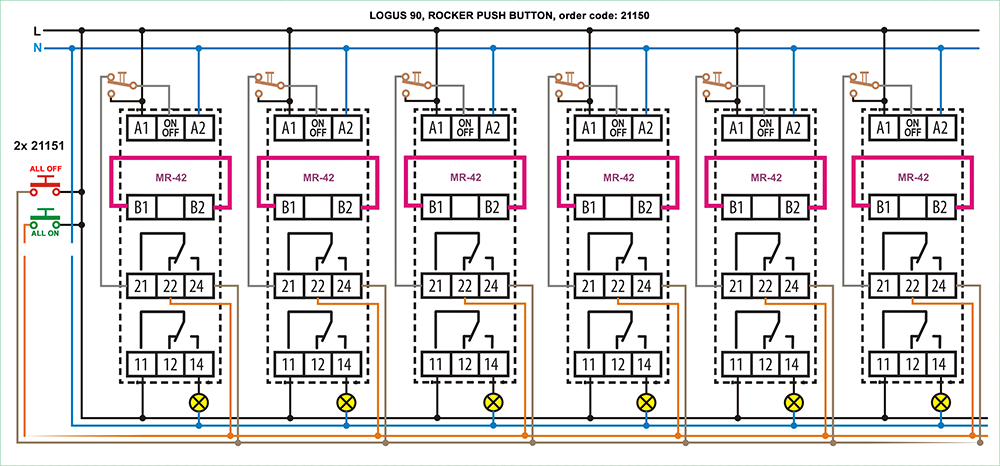
In Figure 1, six lighting circuits are controlled with pulse relays, so that the individual circuits can be controlled separately, independently of each other, or in group. In order to function correctly, we have to use slightly different solutions from traditional pulse relay installations. The first thing that can be noticed is that it is not a normal push button for the separate control of each circuit, but push buttons with changeover contacts - such as e.g. type 21151 available in the LOGUS90 design. The reason for its use is to separate the individual controls from the common control wires. In a basic situation, therefore, priority is given to joint control.
Img. no.1 - click to enlarge
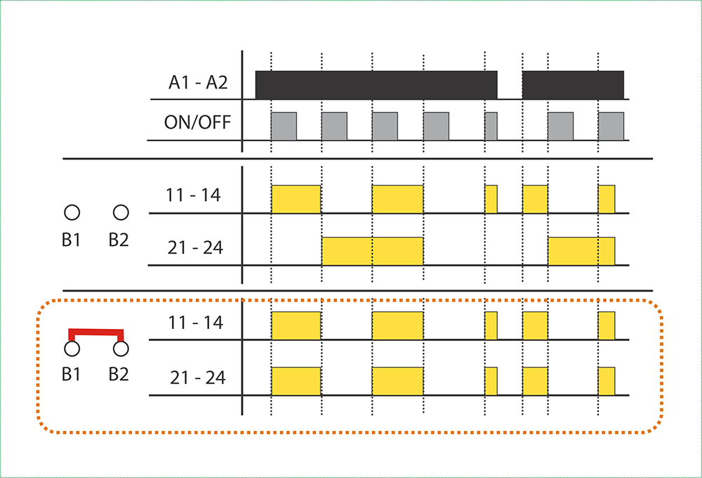
The other important difference is that we use the pulse relay type MR-42, with two potential-free and independent changeover contacts, which we have already incorporated several times in our previous circuits. It is basically a pulse relay, but by connecting terminals B1 - B2, we "program" the two relays for parallel operation - see Figure 2. Channel 1 of the pulse relay switches the corresponding lighting circuit, while channel 2 provides information about the status of the given pulse relay to the common control, i.e. it "shows" whether the particular lighting circuit is switched on or off.
Img. no.2 - Click to enlarge
How it works?
The local push buttons can be used to directly change the state of the pulse relay associated with the push button, and in the default state it "enables" the common control in the direction opposite to its current state. Thanks to the toggle contact buttons, joint control can only take effect if the local buttons are in their default position, i.e. not pressed. Only channel 2 of the pulse relay transmits a signal to the ON/OFF input, which is in a state opposite to the function of the pressed "All On" or "All Off" common pushbutton:
- if the "All On" button is pressed, the pulse relays that are on will not respond, and those that are off will turn on.
- if the "All Off" button is pressed, the pulse relays that are switched off will not respond, and those that are switched on will be switched off.
When interpreting the operation, consider that the ON/OFF input works on a rising edge, so the pulse relay switches when the control voltage appears, and it doesn't matter how long the voltage remains on it. The relay does not react to switching off the control signal.
The "All On" and "All Off" push buttons designed in the drawing are the LOGUS90 design 21151 normal push button type.
In the connection above, separate push buttons were used for common on and off.
If it's a pulse relay, it would be nice to control everything, including the common control, with a "one-button". In our next letter, we will show you a possibility for this.
In our current letter, we continue our thoughts on the joint control of pulse relay lighting. In the push-button or switch control of "real" smart houses, almost all options can be selected or implemented by programming, and it is even possible to combine them. Thus, a lighting circuit in a smart house can be controlled traditionally, i.e. with a simple single-pole switch and/or with two separate switches and/or with a push button in the form of a pulse relay and/or with a separate on and off push button, as can be seen in the circuit diagram of the previous letter. But you can also manipulate the number of button presses or the duration of the button presses. By further "smartening" the circuit diagram of our previous letter with a small modification, we show how the one-button common on and off can also be solved with pulse relay control.
A "smart" time relay solves everything
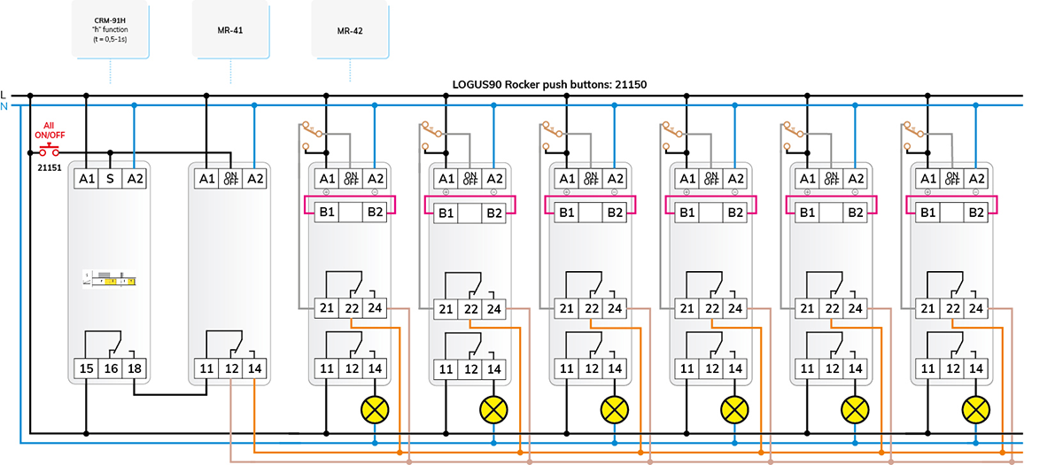
The circuit diagram in Fig. 3 shows the additions and modifications that are necessary to convert the basic circuit described in the previous letter to one-button control.
Img. no.3 - click to enlarge
The push buttons with change-over contacts remain for independent control, but a traditional NO contact push button is sufficient for joint control. Of course, it is only sufficient if we resolve that there is no voltage on the two common control wires, that no voltage remains in the default position, otherwise it would not be possible to control the individual circuits independently, - so the common control signal must be sent to the inputs of the relays as a pulse.
This pulse is provided by the already well-known CRM-91H (230 V or UNI) multifunctional time relay, while the on/off one-button common control is provided by an actual pulse relay, the MR-41 (230 V or UNI).
How it works?
The operation of the independent control is the same as the basic operation of the MR-42 (230 V or UNI) - in parallel mode (B1 - B2 connected), as in the previous connection. The operation of the common control can be clearly seen in the circuit diagram of Figure 3 and the operation diagram of Figure 4.
The switch buttons of the independent control still "enable" the joint control in the idle, default position. By pressing the push button of the common control, the "S" input of the time relay and the ON/OFF input of the MR-41 receive a start signal at the same time. The output of the MR-41 switches, but no voltage appears on it yet, because the output of the time relay does not yet switch to it due to the delayed switching.
When the time relay is set to the "h" function, it will operate with a delay switch on of "t" duration and a release-delay of the same duration "t", i.e. it will delay for "t" with the output turned off, then its output will turn on, which will remain on for "t" and then the relay turns off.
The initial "idle" delay is necessary so that the relays have time to switch to the other state and the pulse relays do not switch incorrectly before switching.
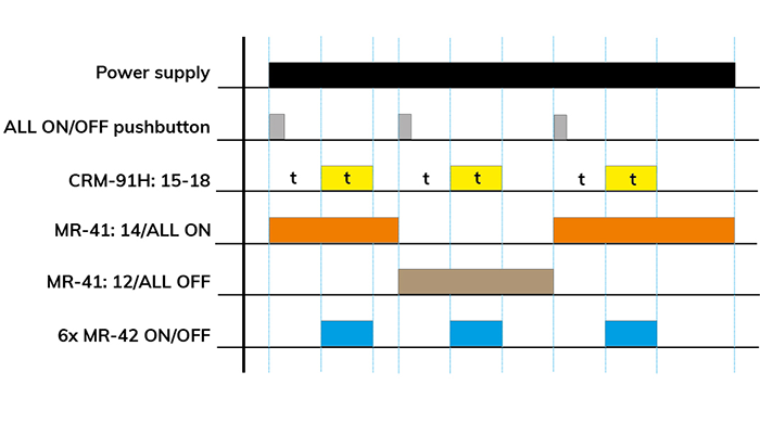
Img. no.4 - click to enlarge
The time relay thus supplies the delayed pulse necessary for switching the MR-42 relays, and the changeover contact of the MR-41 stores the state before the next button press as a digital, one-bit memory.
To be continued…